Reading and writing with spi interface and two micros

This time we use two PIC 18F4550 with one 25aa020a write the memory and the other one we read, we will use a switch to coordinate reading and writing.

for this program we will need to set the spi interface. For this there are two ways:
1 – we can use the setup_spi instruction.
ej.setup_spi (spi_MASTER | spi_L_to_H | spi_clk_div_16 | SPI_XMIT_H_TO_L)
Here we configure the micro as a master, the communication starts at the falling edge, the transmission speed is 16 times less than the clock speed.
with this option, we can use the spi_read guidelines and spi_write to configure the program chosen.

2way choice for us is to use spi settings.
eg. # use SPI (MASTER, DI = PIN_D1, DO = PIN_D2, CLK = PIN_D3, MODE = 0, BITS = 8, IDLE = 0).
Here we configure the micro as a master, the pins used for data transmission, data input DI, DO output data, clock, transmit bits 8 and that will break the clock.With this configuration you can only use the command to write spi_xfer so as to read


memo spi

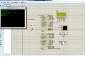
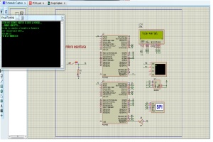
First configure the micro writing, in this case the switch is pressed.
We write in the Hyperterminal desired phrase, no more than 32 characters is the maximum that showing alphanumeric lcd.

First configure the micro writing, in this case the switch is pressed.
We write in the Hyperterminal desired phrase, no more than 32 characters is the maximum that showing alphanumeric lcd.
The program will see the first thing we do is delete the first 33 characters of writing to memory ff.

///////////////////////////////////////////////////////////////////////////////////////////
//   AUTOR: sergio saiz                                             Octubre/2013
///////////////////////////////////////////////////////////////////////////////////////////
//   PROGRAMA:    MAESTRO  esclavo SPI                                     VERSIÓN:    1.0
//   DISPOSITIVO: PIC 18F4550                                  COMPILADOR:    CCS vs4.023
//   Entorno IDE: MPLAB v8.89                                  SIMULADOR:    Proteus 8.0 sp1
//   TARJETA DE APLICACIÓN: Trainer                           DEBUGGER:    ICD3
///////////////////////////////////////////////////////////////////////////////////////////
///////////////////////////////////////////////////////////////////////////////////////////
///////////////////////////////////////////////////////////////////////////////////////////
//                   Estudio de la comunicación del bus serie SPI                            //
///////////////////////////////////////////////////////////////////////////////////////////
///////////////////////////////////////////////////////////////////////////////////////////
// CABECERA ///////////////////////////////////////////////////////////////////////////////
///////////////////////////////////////////////////////////////////////////////////////////

#include <18f4550.h>
#FUSES INTHS, MCLR  //reloj de alta velocidad
#use delay(internal=8Mhz)// Selecciona la velocidad del oscilador interno
#use SPI(MASTER, CLOCK_HIGH= 1, DI= PIN_D1, DO= PIN_D2, CLK= PIN_D3, MODE= 0, BITS= 8, IDLE= 0)
#use rs232(baud=9600,parity=N,xmit=PIN_C6,rcv=PIN_C7,bits=8)//configuracion del rs232
#include<C:\Users\troner\Desktop\sjd2\Desarrolo de prototipos\sistema _mc_2014\proyectos mplab\sexto proyecto leer y escribir spi\LCD_flexible.c>
////////////////////////////////////////////////////////////////////////////////////
// VARIABLES GLOBALES //////////////////////////////////////////////////////////////
////////////////////////////////////////////////////////////////////////////////////
char dato;
char frase[15];//string de 15 caracteres que usaremos para sacarlo x la primera linea del lcd
char sfrase[15];//usamos para segunda linea
int i=0;//inicializamos a 0 la variable numerica
int borrado=0;
int pos=0;
int spos=0;
////////////////////////////////////////////////////////////////////////////////////
// FUNCIONES ///////////////////////////////////////////////////////////////////////
////////////////////////////////////////////////////////////////////////////////////

////////////////////////////////////////////////////////////////////////////////////
// PRINCIPAL ///////////////////////////////////////////////////////////////////////
////////////////////////////////////////////////////////////////////////////////////
void main()
{
lcd_init();
output_high(PIN_A0);//ponemos cs en alto desactivando la eeprom
puts(«ESPERA UNOS SEGUNDOS MIENTRAS SE BORRA LA MEMORIA…\n»);
for(borrado=0;borrado<=33;borrado++)//reescribimos 33 datos de memoria porque son los maximos que mostramos por el lcd
{
output_low(PIN_A0);//escucha(ponemos el cs en bajo seleccionando la eeprom)
spi_xfer(6);//configuracion wren proteccion escritura QUITADA wren 0b00000110(6)
output_high(PIN_A0);//ponemos el cs en alto para desactivar el cs y que se grave la eeprom con la instruccion
delay_ms(10);//tiempo minimo de grabacion 5ms aunq con el reloj a 8mhz tarda un ciclo maquina 0,5ms
output_low(PIN_A0);//escucha
spi_xfer(2);//comando escritura 0b00000010
spi_xfer(i);//direccion escritura
spi_xfer(0xff);//dato a escribir,borrar dato con ff 0b11111111
output_high(PIN_A0);
i++;//incrementa la variable entera que usamos para la direccion de memoria
output_low(PIN_A0);
spi_xfer(0b00000100);//reestablece la proteccion de la escritura
output_high(PIN_A0);
delay_ms(10);
}
i=0;//si la variable que nos indica la direccion de la memoria es la primera
puts(«…BORRADO COMPLETADO…\n»);
puts(«Escriba los caracters a transmitir en la memoria\n»);
puts(«para finalizar pulse enter…\n»);
while(1)
{
dato=getc();//char dato=dato que esta en el buffer del teclado
putc(dato);//escribe en el hiperterminal el char dato

if(spos<16)//si la variable spos vale menos de 16 por que 16 son los byte maximos que se ven en el lcd
{
if(pos<15)//si la variable pos vale menos de 15
{
frase[pos]= dato;//el caracter frase se escribe con el valor del dato en cada posicion de la variable entera pos
pos++;//aumenta la posicion de la variable pos que usaremos para la siguiente posicion del char frase

}
else//si la variable pos vale mas de 15
{
sfrase[spos]= dato;//sfrase se escribe con el valor de  dato en cada posicion de spos
spos++;    //aumenta la posicion de spos que usaremos para la siguiente posicion del char sfrase
}
}
output_low(PIN_A0);//escucha
spi_xfer(6);//configuracion wren proteccion escritura QUITADA wren
output_high(PIN_A0);//graba
delay_ms(5);
output_low(PIN_A0);//escucha
spi_xfer(2);//comando escritura
spi_xfer(i);//direccion escritura
spi_xfer(dato);//dato a escribir
output_high(PIN_A0);
i++;//incrementa direccion
output_low(PIN_A0);
spi_xfer(0b00000100);//proteccion escritura
output_high(PIN_A0);
if(dato == 0x0D)//si el dato es igual a enter
{
lcd_gotoxy(1,1);//escribe en la primera linea del lcd
printf(lcd_putc,»%s»,frase);//escribe el string frase que creamos antes con el algoritmo
lcd_gotoxy(1,2);//escribe en la segunda linea del lcd
printf(lcd_putc,»%s»,sfrase);//escribe el string
puts(«FIN DE LA TRANSMISION»);
for(;;);     //mantente en espera
}

}
}

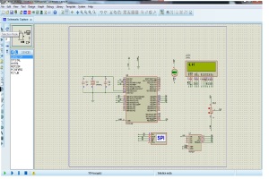
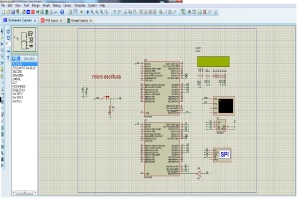
In the case of reading from memory, the switch must be without pressing, so after making the writing part, got the switch and automatically read the memory and the data is written to the lcd.

///////////////////////////////////////////////////////////////////////////////////////////
//   AUTOR: sergio saiz                                             Octubre/2013
///////////////////////////////////////////////////////////////////////////////////////////
//   PROGRAMA:    MAESTRO  esclavo lectura SPI                                     VERSIÓN:    1.0
//   DISPOSITIVO: PIC 18F4550                                  COMPILADOR:    CCS vs4.023
//   Entorno IDE: MPLAB v8.89                                  SIMULADOR:    Proteus 8.0 sp1
//   TARJETA DE APLICACIÓN: Trainer                           DEBUGGER:    ICD3
///////////////////////////////////////////////////////////////////////////////////////////
///////////////////////////////////////////////////////////////////////////////////////////
///////////////////////////////////////////////////////////////////////////////////////////
//                   Estudio de la comunicación del bus serie SPI                            //
///////////////////////////////////////////////////////////////////////////////////////////
///////////////////////////////////////////////////////////////////////////////////////////
// CABECERA ///////////////////////////////////////////////////////////////////////////////
///////////////////////////////////////////////////////////////////////////////////////////

#include <18f4550.h>
#FUSES INTHS, MCLR  //reloj de alta velocidad
#use delay(internal=8Mhz)// Selecciona la velocidad del oscilador interno
#use SPI(MASTER, CLOCK_HIGH= 1, DI= PIN_D1, DO= PIN_D2, CLK= PIN_D3, MODE= 0, BITS= 8, IDLE= 0)
#include<C:\Users\troner\Desktop\sjd2\Desarrolo de prototipos\sistema _mc_2014\proyectos mplab\sexto proyecto parte lectura spi\LCD_flexible.c>
////////////////////////////////////////////////////////////////////////////////////
// VARIABLES GLOBALES //////////////////////////////////////////////////////////////
////////////////////////////////////////////////////////////////////////////////////
char dato;

int i=0;//inicializamos a 0 la variable numerica
int pos=0;
int spos=0;
int x=0;
////////////////////////////////////////////////////////////////////////////////////
// FUNCIONES ///////////////////////////////////////////////////////////////////////
////////////////////////////////////////////////////////////////////////////////////

////////////////////////////////////////////////////////////////////////////////////
// PRINCIPAL ///////////////////////////////////////////////////////////////////////
////////////////////////////////////////////////////////////////////////////////////
void main()
{
lcd_init();
lcd_putc(‘\f’);

while(1)
{
if(spos<16)//si la variable spos vale menos de 16 por que 16 son los byte maximos que se ven en el lcd
{
if(pos<15)//si la variable pos vale menos de 16
{
pos++;
printf(lcd_putc,»%c»,dato);

}
else//si la variable pos vale mas de 15
{
lcd_gotoxy(x,2);
printf(lcd_putc,»%c»,dato);
spos++;    //aumenta la posicion de spos que usaremos para la siguiente posicion del char sfrase
x++;
}
}
output_high(PIN_A0);termina la opcion de lectura poniendo el cs en alto
output_low(PIN_A0);//escucha pon el cs a bajo y comienza la lectura
spi_xfer(0b00000011);//configuracion lectura
delay_ms(5);
spi_xfer(i);//direccion lectura que empieza en la direccion 0 e incrementa con la i
dato=spi_xfer();//dato leido es igual a la vairable dato
if(dato == 0x0D)//si el dato es igual a enter
{
for(;;);     //mantente en espera
}
i++;//incrementa direccion
}
}
memospi2

memospi3

Explanation of SPI hardware

The Serial Peripheral Interface bus or SPI bus is a synchronous serial data link de facto standard , named by Motorola, that operates in full duplex  mode. Devices communicate in master/slave  mode where the master device initiates the data frame. Multiple slave devices are allowed with individual slave select lines. Sometimes SPI is called a four-wire serial bus, contrasting with three, two-, and one wire serial buses. SPI is often referred to as SSI (Synchronous Serial Interface).

The SPI bus specifies four logic signals:

  • SCLK: serial clock (output from master);
  • MOSI: master output, slave input (output from master);
  • MISO: master input, slave output (output from slave);
  • SS: slave select (active low, output from master).

Alternative naming conventions are also widely used:

  • SCLK: SCK, CLK: serial clock (output from master)
  • MOSI: SIMO, SDO, DO, DOUT, SO, MTSR: serial data out; data out, serial out, master transmit slave receive
  • MISO: SOMI, SDI, DI, DIN, SI, MRST: serial data in; data in, serial in, master receive slave transmit
  • SS: nCS, CS, CSB, CSN, nSS, STE, SYNC: chip select, slave transmit enable (active low, output from master)

The SDI/SDO (DI/DO, SI/SO) convention requires that SDO on the master be connected to SDI on the slave, and vice versa. Chip select polarity is rarely active high, although some notations (such as SS or CS instead of nSS or nCS) suggest otherwise.

SPI port pin names for particular IC products may differ from those depicted in these illustrations.

The master does not use an addressing concept while communicating with the slave

spi_interface_5

Data transmision

Explanation of i2c protocol

we will use the i2c protocol for this first exercise. I²C (Inter-Integrated Circuit, referred to as I-squared-C, I-two-C, or IIC) is a multimaster-serial single-ended computer-bus invented by Philips used for attaching low-speed peripherals to a motherboard, embedded system, cellphone, or other electronic device. I²C uses only two bidirectional open-drain lines, Serial Data Line (SDA) and Serial Clock (SCL), pulled up with resistor. Typical voltages used are +5 V or +3.3 V although systems with other voltages are permitted. The I²C reference has a 7-bit or a 10-bit (depending on the device used) adderess space . Common I²C bus speeds are the 100 kbit/s standard mode and the 10 kbit/s low-speed mode, but arbitrarily low clock frequencies are also allowed. Recent revisions of I²C can host more nodes and run at faster speeds (400 kbit/s Fast mode, 1 Mbit/s Fast mode plus or Fm+, and 3.4 Mbit/s High Speed mode). These speeds are more widely used on embedded systems than on PCs. There are also other features, such as 16-bit addressing. The exercise is to use the i2c protocol for a lcd read an A / D and in this case I chose to do the exercise in autoincrement mode. In this mode the inputs are compared among themselves índice The before mentioned reference design is a bus with a clock (SCL) and data (SDA) lines with 7-bit addressing. The bus has two roles for nodes: master and slave:

  • Master node — node that generates the clock and initiates communication with slaves
  • Slave node — node that receives the clock and responds when addressed by the master

The bus is a multi-master bus which means any number of master nodes can be present. Additionally, master and slave roles may be changed between messages (after a STOP is sent). There are four potential modes of operation for a given bus device, although most devices only use a single role and its two modes:

  1. master transmit — master node is sending data to a slave
  2. master receive — master node is receiving data from a slave
  3. slave transmit — slave node is sending data to the master
  4. slave receive — slave node is receiving data from the master

The master is initially in master transmit mode by sending a start bit followed by the 7-bit address of the slave it wishes to communicate with, which is finally followed by a single bit representing whether it wishes to write(0) to or read(1) from the slave. If the slave exists on the bus then it will respond with an ACK bit (active low for acknowledged) for that address. The master then continues in either transmit or receive mode (according to the read/write bit it sent), and the slave continues in its complementary mode (receive or transmit, respectively). The address and the data bytes are sent most significant bit first. The start bit is indicated by a high-to-low transition of SDA with SCL high; the stop bit is indicated by a low-to-high transition of SDA with SCL high. All other transitions of SDA take place with SCL low. If the master wishes to write to the slave then it repeatedly sends a byte with the slave sending an ACK bit. (In this situation, the master is in master transmit mode and the slave is in slave receive mode.) If the master wishes to read from the slave then it repeatedly receives a byte from the slave, the master sending an ACK bit after every byte but the last one. (In this situation, the master is in master receive mode and the slave is in slave transmit mode.) The master then either ends transmission with a stop bit, or it may send another START bit if it wishes to retain control of the bus for another transfer (a «combined message»).

Third activity conversor a/d using the hardware SPI

In this practice we learn to use the spi interface, the practice is similar to what we did with the i2c, a converter a / d this time we will use the library containing the SCCS for use converter.
Configure the frequency with an external crystal because the capacitor discharge information takes little time and in poor use the 8MHz information to be lost. This information is in the dataseet of mcp3204.

///////////////////////////////////////////////////////////////////////////////////////////
//   AUTOR: sergio saiz                                             Octubre/2013
///////////////////////////////////////////////////////////////////////////////////////////
//   PROGRAMA:    MAESTRO SPI                                     VERSIÓN:    1.0
//   DISPOSITIVO: PIC 18F4550                                  COMPILADOR:    CCS vs4.023
//   Entorno IDE: MPLAB v8.89                                  SIMULADOR:    Proteus 8.0 sp1
//   TARJETA DE APLICACIÓN: Trainer                           DEBUGGER:    ICD3
///////////////////////////////////////////////////////////////////////////////////////////
///////////////////////////////////////////////////////////////////////////////////////////
///////////////////////////////////////////////////////////////////////////////////////////
//                   Estudio de la comunicación del bus serie SPI                            //
///////////////////////////////////////////////////////////////////////////////////////////
///////////////////////////////////////////////////////////////////////////////////////////
// CABECERA ///////////////////////////////////////////////////////////////////////////////
///////////////////////////////////////////////////////////////////////////////////////////

#include <18F4550.h>
#FUSES xt
#use delay(clock=20Mhz)// Selecciona la velocidad del oscilador interno
#include <mcp3204.c>//LIBRERIA DEL CONVERSOR A/D
#include<C:\Users\troner\Desktop\sjd2\Desarrolo de prototipos\sistema _mc_2014\proyectos mplab\quinto proyecto_spi lector analog\LCD_flexible.c>
////////////////////////////////////////////////////////////////////////////////////
// VARIABLES GLOBALES //////////////////////////////////////////////////////////////
////////////////////////////////////////////////////////////////////////////////////
float value;//VARIABLE NUMERICA TIPO FLOAT PARA SACAR VALORES DECIMALES
float valor;
////////////////////////////////////////////////////////////////////////////////////
// FUNCIONES ///////////////////////////////////////////////////////////////////////
////////////////////////////////////////////////////////////////////////////////////

////////////////////////////////////////////////////////////////////////////////////
// PRINCIPAL ///////////////////////////////////////////////////////////////////////
////////////////////////////////////////////////////////////////////////////////////
void main()
{

adc_init();//ACTIVACION DEL CONVERSOR A/D
lcd_init();//ACTIVACION DEL LCD FLEXIBLE
while(1)
{
lcd_gotoxy(1,1);
value = read_analog_mcp(0,1);//ELEGIMOS CANAL 0 CON(0),CON(1)ELEGIMOS DIFENCIAR CON GND FORMA SINGEL
valor=(value*5)/4096;//OPERACION DE CONVERSION DE LOS DATOS LEIDOS PARA SACARLOS TIPO DECIMAL X EL LCD,DIVIDIMOS EL VALOR MAXIMO DE VOLTAJE ENTRE LOS BIT MAXI.
printf(lcd_putc»%f»,valor);//SACAR POR EL LCD FLEXIBLE LOS DATOS LEIDOS DE LA VARIABLE VALOR
}
}

Sin título jurjur

Second practice i2c memory

The previous practice (convert to / d) explain the i2c protocol, this practice had to explain the exercise directly.

In this practice we write in eeprom using i2c protocol, then proceed to reading and showing it for extraction lcd. Continue using the Mplab compiler program and the CCSC.The program works by typing in Hyperterminal, memory is recorded and proceed to read the memory and we get the lcd.

PROGRAM.

///////////////////////////////////////////////////////////////////////////////////////////
//   AUTOR: sergio saiz                                              Octubre/2013
///////////////////////////////////////////////////////////////////////////////////////////
//   PROGRAMA:    I2C                                             VERSIÓN:    1.0
//   DISPOSITIVO: PIC 18F4550                                  COMPILADOR:    CCS vs4.023
//   Entorno IDE: MPLAB v8.89                                  SIMULADOR:    Proteus 8.0 sp1
//   TARJETA DE APLICACIÓN: Trainer                           DEBUGGER:    PICKIT3
///////////////////////////////////////////////////////////////////////////////////////////
///////////////////////////////////////////////////////////////////////////////////////////
///////////////////////////////////////////////////////////////////////////////////////////
//    Estudio de la comunicación I2C con la memoria CMOS EEPROM 24LC256 de MICROCHIP     //
///////////////////////////////////////////////////////////////////////////////////////////
///////////////////////////////////////////////////////////////////////////////////////////
// CABECERA ///////////////////////////////////////////////////////////////////////////////
///////////////////////////////////////////////////////////////////////////////////////////

#include <18f4550.h>//micro usado
#fuses intHS,MCLR//fusibles alta velocidad para poder manejar mas datos y master clear
#use delay(internal=8MHz)//reloj
#use i2c(Master, sda=PIN_B0, scl=PIN_B1)//configuracion de pines del i2c
#use rs232(baud=9600,parity=N,xmit=PIN_C6,rcv=PIN_C7,bits=8)//configuracion del rs232
#include<C:flexible.c>
///////////////////////////////////////////////////////////////////////////////////////////
// VARIABLES GLOBALES /////////////////////////////////////////////////////////////////////
///////////////////////////////////////////////////////////////////////////////////////////
int DIR_H=0;//direccion de byte mayor peso
int DIR_L=0;//direccion byte de menor peso
char RECIB;//variable de 8 bit
char mensaje;//variable de 8 bit
int i=1;//variable numerica para cuenta de caracteres de lectura
int x=0;//variable numerica para cuenta de caracteres de escritura

///////////////////////////////////////////////////////////////////////////////////////////
// FUNCIONES //////////////////////////////////////////////////////////////////////////////
///////////////////////////////////////////////////////////////////////////////////////////

///////////////////////////////////////////////////////////////////////////////////////////
// PRINCIPAL //////////////////////////////////////////////////////////////////////////////
///////////////////////////////////////////////////////////////////////////////////////////
void main()//programa principal
{
lcd_init();//activacion del lcd
puts(«Escribe los caracteres a transmitir\n»);//dialogo que aparece en hiperterminal
puts(«Para finalizar pulse ENTER…\n»);
WHILE(1)//ciclo
{
RECIB=GETC(); //variable RECIB es igual a un caracter guardado el buffer del teclado
PUTC(RECIB);//escribo en el hiperterminal el caracter de la variable RECIB
I2C_START();//condicion de inicio de i2c
I2C_WRITE(0XA0);//direccion de la memoria esclavo a escribir
I2C_WRITE(DIR_H);//valor del byte de mayor peso(antes inicializado a 0 como el byte de menor peso)
I2C_WRITE(DIR_L);//valor del byte de menor peso que aumenta con cada caracter de RECIB al hacer el ciclo while
x++;//variable numerica que aumenta con cada ciclo de while
lcd_putc(‘\f’); //borrado de lcd

//Pregunto si es ENTER…———————–

if(RECIB==0x0D)//si el caracter de la variable RECIB es enter
{
DIR_L=0;//la direccion de byte baja se reinicia en la posicion 0 de memoria
puts(«fin de transmision\n»);//pon en el hiperterminal fin de transmision
I2C_START();//condicion de inicio de i2c
I2C_WRITE(0XA0);//direccion de esclavo
I2C_WRITE(DIR_H);//valor de byte alto=0
I2C_WRITE(DIR_L);//valor de byte de direccion de memoria bajo empieza en 0
I2C_START();//condicion de inicio repetida
I2C_WRITE(0b10100001);    //configuracion de esclavo memoria 24lc256 para leer
while(1)//bucle
{
i++;//variable numerica que aumenta cada vez que se realiza este bucle
mensaje=i2c_read();//la variable mensaje es igual al caracter que lee el i2c
printf(lcd_putc»%c»,mensaje);//saca por el lcd el valor del caracter mensaje leido
delay_ms(100);//esper a sacar el caracter por el lcd
if(i==x)//compara la variable numerica de la escritura y la de la lectura y si es igual entra en el bucle
{
for(;;);
}

}
}
i2c_write(RECIB);//escribe en la memoria del esclavo el caracter RECIB
i2c_stop();//condicion de parada,para que pueda seguir escribiendo otro caracter
DIR_L++;//aumenta en 1 posicion la direccion para escribir otra variable de RECIB(getchar) en la memoria
}
}

título

First activity conversor i2c a/d diferencial mode

This is our first practice with mplab program and using the CCSC compiler.
decided to conduct a digital analog converter converosr with PCF8591.
in my case I decide to use multiple read potential and differential mode

/////////////////////////////////////////////////////////////////////////////////////////////////////
//   AUTOR: sergio saiz                                              Octubre/2013

This is our first practice with mplab program and using the CCSC compiler.
decided to conduct a digital analog converter converosr with PCF8591.
in my case I decide to use multiple read potential and differential mode

///////////////////////////////////////////////////////////////////////////////////////////
//   PROGRAMA:    I2C                                             VERSIÓN:    1.0
//   DISPOSITIVO: PIC 18F4550                                  COMPILADOR:    CCS vs4.023
//   Entorno IDE: MPLAB v8.89                                  SIMULADOR:    Proteus 8.0 sp1
//   TARJETA DE APLICACIÓN: Trainer                           DEBUGGER:    PICKIT3
///////////////////////////////////////////////////////////////////////////////////////////
///////////////////////////////////////////////////////////////////////////////////////////
///////////////////////////////////////////////////////////////////////////////////////////
//    Estudio de la comunicación I2C con la memoria CMOS EEPROM 24LC256 de MICROCHIP     //
///////////////////////////////////////////////////////////////////////////////////////////
///////////////////////////////////////////////////////////////////////////////////////////
// CABECERA ///////////////////////////////////////////////////////////////////////////////
///////////////////////////////////////////////////////////////////////////////////////////

#include<18f4550.h>//libreria del micro elegido
#fuses INTHS,MCLR, //Reloj interno alta velocidad y Master clear
#use delay(internal=8mhz)//frecuencia reloj a 8mhz
#use i2c(Master,SDA=PIN_B0,SCL=PIN_B1)   //configuracion de i2c
#include<C:\Users\troner\Desktop\sjd2\Desarrolo de prototipos\sistema _mc_2014\proyectos mplab\incrremento con i2c\LCD_flexible.c>
int dato1;//variables
int dato2;
int dato3;
int dato4;
float voltaje1;
float voltaje2;
float voltaje3;
float voltaje4;
void main()
{
lcd_init();//inicializo el lcd
i2c_start();//inicio de comunicacion,hola
i2c_write(0b10010000);//direccion del pcf 8591
i2c_write(0b00000100);//selecciono canal 0,con autoincremento y desabilito la salidas analogicas,escojo la entrada AIN0
i2c_start();//condicion de inicio repetida para trabajar con los datos
i2c_write(0b10010001);//direccion del 8591 y escojo que me trasnsmita sus datos entrantes
for(;;)
{
//el rango de funcionamiento es el vref divides la vin de ain0….entre la vref y eso  lo divides entre 2,56(para ser visible por el usuario)ylo que te da es la constante para la formula 0,039
dato1=i2c_read();//configuracion de lectura
voltaje1=dato1*0.0039;//voltaje1 multiplicado por el resultado del voltaje entre los bits(1v/256=0.0039)
lcd_gotoxy(1,1);//linea 1 posicion 1 del lcd
printf(lcd_putc»                «);//borra lcd
lcd_gotoxy(1,1);
printf(lcd_putc»voltios1=%1.3fv»,voltaje1);//saca por el lcd un digito y tres decimales de la variable voltaje1
delay_ms(1500);
dato2=i2c_read();
voltaje2=dato2*0.0039;
lcd_gotoxy(1,1);
printf(lcd_putc»            «);//borrar lcd
lcd_gotoxy(1,1);
printf(lcd_putc»voltios2=%1.3fv»,voltaje2);
delay_ms(1500);
dato3=i2c_read();
voltaje3=dato3*0.0039;
lcd_gotoxy(1,1);
printf(lcd_putc»            «);//borrar lcd
lcd_gotoxy(1,1);
printf(lcd_putc»voltios3=%1.3fv»,voltaje3);
delay_ms(1500);
dato4=i2c_read();
voltaje4=dato4*0.0039;
lcd_gotoxy(1,1);
printf(lcd_putc»            «);//borrar lcd
lcd_gotoxy(1,1);
printf(lcd_putc»voltios4=%1.3fv»,voltaje4);
delay_ms(1500);

Sin título